
Module 6: External solid wall insulation
Modules
1. Comfort, sound insulation and resilience ![]()
2. Overheating ![]()
3. Pitched roof insulation ![]()
4. Flat roof insulation ![]()
5. Internal solid wall insulation ![]()
6. External solid wall insulation
7. Timber framed wall insulation
8. Suspended floor insulation
9. Air tightness and the use of tapes
10. Use of vapour control membranes
11. Maintenance and design
12. Choosing the right systems
Need Materials?
If you’re working on a building project and need help specifying your materials, checkout the following.
Overview
External insulation is the simplest solution to insulating solid walls. Because the insulation is warming up the existing masonry you massively reduce the risks of moisture accumulation from condensation. If you combine this with a breathable and very capillary active type of insulation, such as wood fibre, then you have a building that will dry out quickly after installation and that will stay dry in the future.
Applying external insulation to a wall also allows the existing masonry structure to be within the insulation envelope and therefore maintain the thermal mass of the building. This will help keep a steady, comfortable environment inside and buffer large external temperature variations and in the long term, reduce your heating bill.
However, as applying insulation to the exterior of a building changes it’s appearance it is important to check whether this is acceptable to any planning authority or if it has an impact on any neighbouring property. Roof and verge overhangs will also need to be increased if they do not adequately cover the insulation.
Assessment of the building
Starting at the base of the wall, external ground levels are always best below internal floor levels by around 150mm if possible. If this is not the case and its possible to lower the ground levels then this should be part of the insulation works. Additionally, drainage along the bottom of the wall is very important, particularly if the insulation system is going to be installed below ground level. A gravel drain should be installed to ensure adequate drainage if there is not enough fall around the building to drain naturally.
Should the external ground level have to remain above internal finished floor level then high density XPS, such as Styrodur plinth insulation, should be used along the plinth externally, starting well below floor level up to 300mm above ground level, and then rendered with a waterproof render prior to having a drainage membrane placed up against it. Any gaps between the ground and the wall should be filled with gravel to allow drainage.
Window sills can represent a big thermal bridge around openings and so if concrete or stone sills are present they should be cut off during the works and replaced with either the aluminium system sills or with insulated GRP stone effect sills. The GRP sills are a very good likeness for natural stone or concrete so could be used to keep the character of the building if required.
External services such as down pipes or drain pipes should not run through the insulation and should be extended outwards to run along the surface of the insulation. Main electrical cables should never be buried behind insulation so ensure a suitable fixing, such as Swifix SWI-ST connection point fitting or Fischer Thermax, is installed to take the load of the cable.
Roof overhangs must be adequate to cover the insulation and provide an overhang of at least 40mm. If the existing roof does not offer this then either the roof should be extended or a metal capping profile, such as UdiALU profile, should be used.
Projections, such as porches or lean to roofs need careful detailing. If the roof covering can be removed to allow the insulation to carry on down the wall behind and then made good against the insulation surface this would be preferable. However, if this is not possible then a starter track can be used although this does allow the formation of a significant break in the insulation and thermal bridge.
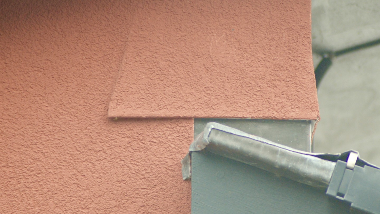
Rigid insulation boards require flat surfaces so the flatness of the wall should be gauged along with the surface texture. If required, use a levelling coat of Baumit RK39 lime base coat render to level the wall surface out.
Alternatively, if using the UdiRECO system, check that the boards will cope with the variation in the surface or use different thickness boards in areas further from the desired line of the wall. Voids deeper than the capabilities of the board should be filled with a hydraulic lime based mortar/plaster and allowed to dry prior to fixing the boards.
Installation
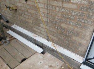
Plinth insulation boards should be bonded to the wall with a cementitious adhesive, such as UdiBASE Plinth Slurry or Baumit StarContact, to ensure that no moisture rises up behind the boards and then continue up to 300mm above ground level. If a DPC is present the plinth boards would normally stop at this point and a wider plinth starter track installed. This allows a drip to be formed at DPC level.
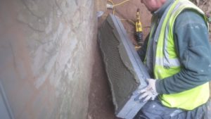
If the plinth insulation needs to continue above DPC, a 25mm deep triangular notch spanning the DPC should be taken out of the back of the plinth boards. This must not be filled with the adhesive as this ensures an air pocket remains at DPC level and prevents moisture rising above the DPC.
At the top of the plinth insulation either install the plinth starter track, such as UdiBASE plinth track, to install a thicker insulation board and create a drip. If this is not required, apply glue to the top edge of the EPS/XPS just before the boards are installed, to ensure a good bond between the wood fibre boards and plinth insulation.
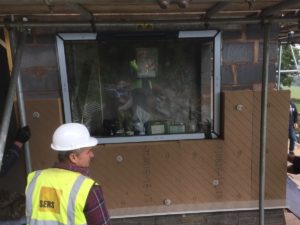
Time spent planning will ensure a more successful installation. Vertical and horizontal joints in the wood fibre boards should be kept a minimum of 300mm from the corners of any openings. Additionally, vertical joints must be staggered by at least 300mm. With this in mind it helps the installation to accurately measure the wall and work out the best height for the first course of boards. It may better to cut them in half horizontally to ensure the horizontal joints are well away from the corners of openings.
Boards should be placed against the wall and lightly fixed with 2 fixings. Fixings are drilled directly through the surface of the board, approximately 100mm from corners and edges, to a depth of at least the length of the fixing plus 20mm. e.g. If you have 115mm fixings, holding a 60mm board then ensure the drill penetrates the board and wall to a depth of at least 135mm. For external insulation 9 fixings per m2 is the normal number of fixings required but please consult system manufacturers guidance to confirm.
Fixings into masonry should penetrate the masonry wall by a minimum of 40mm for hammer type fixings but typically 65mm for the UdiRECO system fixings. For solid boards hammer type fixings such as Ejot STR-U are the cheapest and quickest although on soft masonry such as soft brick, Thermoplan/Porotherm or soft stone, screw fixings such as UdiASSEMBLY Masonry fixings would be advisable.
Once the first board is held in position loosely subsequent boards can be added to the wall, following the same procedure. Vertical joints should be staggered by at least 300mm so it is advisable to install the boards in horizontal rows with the off-cut from one end being used to start the next row at the other end. Complete wall panels fully before moving on to adjacent panels.
Once a board has all it’s neighbouring boards added then the rest of the fixings for that board can be installed. This is to ensure that the tongue and groove connection can be made for each joint as if the boards are tightly fixed first it is very difficult to make that connection later.
Internal corner joints are simply a case of butting the boards tightly against each other and glueing if necessary but external corners require a little more detailing. External corners are a butt-joint which should be made carefully and also glued with specialised glue, such as UdiSPECIAL ADHESIVE. The boards on the first panel should be left to oversail the corner by 5-10mm more than the thickness of the boards so that they can be cut or planed back accurately when the boards on the adjacent panel are installed.
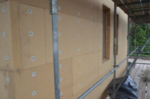
When installing boards up to window openings, horizontal and vertical joints should be kept 300mm from the corners of the opening. If this is not possible then the joints should be glued to prevent cracking.
When installing the top layer of boards up to an existing soffit or eaves, it may be necessary to cut the back part of the groove off of the bottom of the board to enable the board to be fitted. This allows a tight fitting against existing structures but does require the joint to be glued thoroughly.
UdiRECO system
The procedure for installing this system follows the same principles as above but fixing into random stonework is different. To ensure each UdiASSEMBLY masonry fixing is drilled in to stone rather than mortar, the fixing guide should be used. This is a quick process of placing the guide against the wall, marking the preferred fixing positions and then transferring the markings to the surface of the board. This process is repeated for each board.
Each board is fixed loosely and the whole wall panel is boarded as above but as the rest of the fixings are installed the boards are pulled in tight against the wall. Using a vertical laser level or a long spirit level tighten each screw fixing to bring the boards into the correct position. Impact drivers should not be used for installing these fixings as they tend to damage the heads of the screws, preventing further adjustment.
This video shows the basic principle of the system and how the system is simply levelled with a laser (the red line). Press play to view it.
https://woodfibreinsulation.co.uk/wp-content/uploads/2017/01/RECO-Darstellung_kurz.mp4
Internal corners are treated as a simple butt joint however, as above, external corners need careful detailing. Insulation from the first completed wall panel should over-sail the corner but the full depth of the insulation (e.g. 100mm insulation should over-sail the corner by 100mm).
Once all of the fixings have been installed and tightened to the correct position then this corner should be cut in-situ to give an over-sail of the depth of the flexible backing on the board. E.g. for the 100mm board the final depth of the flexible backing will be approximately 60mm. This allows the adjacent panel to form a lap joint which can be glued prior to tightening the fixings.
Window/Door reveals
Window and door reveals are detailed similarly for both of the above systems. The boards should be finished flush with the edges of the openings and a 20 or 40mm wood fibre reveal board should be used to insulate the reveals.
The reveal boards should be bonded in place using the system render as an adhesive on to the masonry areas with system glue used where the boards lap on to the edges of the main insulation boards. Generally the heads are installed first with the sides second. This ensures that the boards don’t drop out of position whilst waiting for the adhesive to set.
Window sills
If using solid sills, such as timber or insulated GRP sills, it is important to seal them against the wood fibre. Jointing tapes or expanding foam tapes, such as Ampacoll Komprimax jointing tape, should be used to seal all the joints around the perimeter of the sill to ensure that there is no moisture leakage. It is very important to size the tape correctly as over-expanded tape is not weather tight.
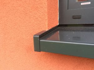
Aluminium sills used must be specifically designed for use with EWI systems and have end caps at each end of the sills to prevent water tracking sideways into the insulation. Additionally, UdiALU sills have a premium end cap that also allows expansion and contraction in the sill. This is especially useful for very long window sills.
Application of the render:-
The application of the render is covered in detail in the next section on insulating timber framed structures.